The originator of the power supply “AT” specification power supply
Like other early products, the AT specification was proposed by IBM. We often say that the 386 486 old machine uses this kind of power supply. This type of power supply is reloaded from the computer Pepsi network with the launch of IBM. When the PC/AT machine was proposed, the time was before the 1990s, the originator of the well-deserved computer switching power supply. This type provides +5V, – reloaded from the computer Pepsi network 5V, +12V, -12V four sets of voltage, with a hard switch. Anyone who has used an old machine such as 386 486 knows that when the power is turned on, it needs to switch a switch on the back of the chassis, and the computer will be powered by the computer. Yes, this kind of power supply can be said to be very mechanical and cannot be software switched. With the development of technology, this type of power supply has now been completely eliminated.
Milestone “ATX” power specification
In 1995, Intel introduced a new motherboard architecture – ATX, followed by the ATX specification of the power supply, and today, we are still using this system of power, but the version has changed. ATX is an abbreviation of English AT Extend and can be translated into AT extension. Compared with AT power supply, it mainly adds +3.3V and +5V Standby two outputs and one PS-ON signal, and can be softly turned off (AT needs to turn off the switch), and the output line is changed into a 20-core cable to supply power to the motherboard. .

ATX has experienced different stages, namely ATX1.01, ATX2.0, ATX2.01, ATX2.02, ATX2.03, ATX 12V (also known as ATX 2.04, ATX2.03 power supply, both of which are Basic updates, such as ATX2.2, ATX2.3.
In fact, ATX has developed to ATX 2.03. The difference between the versions is actually not big. Even in the ATX12V specification, the motherboard power supply mode of this 20Pin core is also used in the early stage.
| VERSION |
DIFFERENCE |
| ATX2.0 |
The air is dissipated by external ventilation, and the 1.01 uses the in-network west wind to dissipate heat. |
| ATX2.01 |
Change the +5V Standby output current from 10mA to 720mA. This change is for the Wake-on-LAN feature. |
| ATX2.02 |
A six-pin auxiliary plug has been added, and the output voltage deviation of -5V and -12V has been changed from +/-5% to +/-10%. |
| ATX2.03 |
The “Micro ATX” in the ATX2.02 version was changed to “Mini ATX” to distinguish it from another standard Micro ATX proposed by Intel. |
As can be seen from the above table, the change from ATX 1.01 to ATX 2.03 is not big, because the development of the computer has not yet entered the PENTIUM4 stage. After the PENTIUM4 stage, the computing speed of the computer begins to develop rapidly, and the power consumption also follows. Go up. The ATX standard, which relies on a 20PIN core to power everything on the board, is becoming more and more stretched, so the wheel of history is rolling forward again.
Long-awaited “ATX12V” specification Strictly speaking, ATX12V is planned within the scope of ATX, but its emergence represents the development of the computer into the “modern history.” The ATX12V is also called ATX 2.04, but it has a separate name – the P4 power supply. In other words, in the face of high power PENTIME4, ATX 12V came into being. ATX 12V, as its name suggests, strengthens the current output capability of the +12VDC terminal, and has made new regulations on the current output of +12V, the peak value of the surge current, the capacity of the filter capacitor, and protection; newly added P4 power connection line; The current output capability of +5VSB; the “serial port” power supply concept also has a prototype at this time.
ATX12V specification, in fact, has also been divided into many versions, they are ATX12V1.2, ATX12V1.3, ATX12V2.0, ATX12V2.2, ATX12V 2.3, ATX12V2.31. Starting from V1.2, the ATX 12V no longer provides a -5V voltage output, because the ISA card slot interface has been withdrawn for various reasons, and the -5V output is not required.
Starting with V1.3, we have added a familiar interface, which is the SATA power port. The power supply on the market now still has this specification. From V1.3 to V2.0, the single 12V output is changed to the dual 12V output. All the way to power the CPU. The power supply interface of the motherboard is increased from 20 pins to 24 pins, which is the main line of power supply for our mainstream 24PIN core motherboard. The extra four pins, the two pins are 12V output, and the 2-pin ground wire (reinforces 12V for the motherboard). The V2.2 version follows the dual 12V design of V2.0, which increases the maximum output standard to 450W, and introduces the 8PIN power supply standard, re-planning the circuit current standard and improving the conversion efficiency.
Version V2.3 further improves the current distribution after CPU and graphics card power consumption changes. V2.31 further enhances the characteristics of balanced load, radiation protection, non-toxic energy saving, etc. It is also the highest version so far. It can be seen that starting from ATX 12V V2.2, it has been a specification we have seen in recent years, dual 12V, one CPU power supply, one peripheral device power supply. However, the release of V2.3 and V2.31 indicates that the development of power supply will lead to high conversion efficiency and green environmental protection.
The development of power supply fans has a lot of attention. The old birds who walked from DIY road will find a common problem. In recent years, the appearance of power supplies, wires, lead wires, heat dissipation methods, etc. have all undergone tremendous changes. Great changes have taken place. It must be said that with the rapid development of PC computer technology and the continuous improvement of performance, many accessories have embarked on a personalized road, adding many elements of YY, bright and colorful, if combined with a transparent or The translucent chassis will make the monotonous host shine. In the past, most of the power supply was made of galvanized sheet. In terms of wiring, the number and type of connectors specified by the manufacturer were directly soldered to the internal motherboard. The heat dissipation was mainly based on 8CM fans, and the 12CM “big windmill” was developed in the later stage. fan.
In fact, if we look at today’s eyes, the previous power supply has many drawbacks. Most of the coatings of such galvanized sheets are not very thick, and the ability to resist decay is not good. When installed, the printed fingerprints may rust in the later stage. If the weather is wet, the fan net cover and the outer casing interface will be Produced rust. Secondly, this “dead” power line mode is not conducive to users to freely increase the number of interfaces according to their own needs, and the redundant wire, not only brings trouble to the wiring, but also affects the heat dissipation of the chassis cooling air duct. effect. The 8CM fan has a large sound and low efficiency, which are some of the “hard injuries” that are now seen. In the development of this similar power supply, there have been some over-products, they have the wire wrapped in snakeskin net, have modular wiring, and 12CM silent fan, some with PWM speed, or manually set speed of the fan. The advent of these over-products has brought new ideas to the development of power supply. Slowly, these technologies have matured and manufacturers have added a beautiful appearance. The new coated shell material has become the power source we see and use now.
The wire wrapped in the high-density snakeskin net makes the wiring more convenient, making the wires that used to be like a mess become neat and tidy. Modularity gives users a greater choice of space, and it is very convenient to freely match the number of interfaces. It is worth mentioning that 12CM fans (in the past, there are similar designs, but most of them are positioned at the high end), not only bring high-efficiency heat dissipation to the power supply, but also suck the residual heat of the CPU and the power supply part of the motherboard, and blow it out of the chassis. Not to mention the finishing touch of power development, breaking the design of the internal components of the chassis, giving a whole, coordinated comfort. Now the design of the power supply can be said to give DIY players ample room to carry forward their personality.
Power parameter
Wire diameter problem
The most intuitive standard for power supply is the wire diameter. The internal current of the computer is actually very large. The output current of 12V is up to several tens of amps. There is no high-quality wire to act as a current channel, not only for hardware. Stable supply of electricity can also lead to safety risks. In general, the wire needs to have 18 AWG, that is, the cross-sectional area should be 1.00 mm2, of course, the thicker the better, the AWG value is generally on the wire insulation skin. (AWG is the abbreviation of American Wire Gauge. The single-wire conductor is based on the diameter, and the strand is determined according to the cross-sectional area.)
Power supply
The power of the power supply can be divided into: rated power, maximum power and peak power. But only the rated power and maximum power have practical significance. Rated power: The ambient temperature is between -5 and 50 degrees, the input voltage is between 180V and 264V, and the power supply can stabilize the output power for a long time. Maximum power: At normal temperature, the input voltage is between 200V and 240V. The power supply can stabilize the output power for a long time. The maximum power is generally about 15% larger than the rated power. Peak power: The maximum power that the power supply can reach in a very short time, and the time can only last between a few seconds and 30 seconds. The peak power is related to the environment and conditions of use. It is not a certain value, but the peak power can be very large, which is very easy to mislead the user and does not have any reference value. Generally speaking, the power supply XXX W mostly refers to the rated power, but there are very few behaviors that will call out the maximum power and even the peak power as a gimmick. It is especially important to polish the eyes.
What is PFC?
PFC English is called “Power Factor Correction”, which means “power factor correction”. Power factor refers to the relationship between effective power and total power consumption (apparent power), that is, the effective power divided by the total power consumption. The ratio of the amount (apparent power). Basically, the power factor can measure the degree to which power is effectively utilized. When the power factor value is larger, it represents the higher the power utilization rate. Generally speaking, the PFC circuit is a circuit that improves the efficiency of the power supply, and is divided into passive PFC and active PFC. Passive PFCs are generally classified as “inductive compensation” and “Valley Fill Circuit”. Both passive PFC circuits have a disadvantage that the power factor can only reach a maximum of 0.9, but at a lower cost. It is also easy to identify it, that is, there is often a piece of iron inside the power supply. In fact, it is not a transformer but a passive PFC.
Relatively speaking, the active PFC is usually more than 98% because it has a dedicated IC control circuit.
What is EMI?
EMI is what we call electromagnetic interference. Now the power of the power supply is getting higher and higher. The internal high current will inevitably produce strong electromagnetic interference. A good power supply needs the help of EMI filter circuit to ensure the stability of the output. A secondary EMI circuit already exists in the power supply.
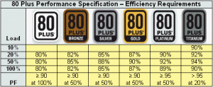
5, 80PLUS standard
As a sign of conversion efficiency, 80PLUS has long been known to the public, but do you know the specific energy efficiency of the various indicators of the 80PLUS?
On each installation order, the chassis power supply is mostly in the last item. When you fully consider the configuration of the overall platform, you should consider the choice of power supply. First of all, in terms of power, try not to “eat and die”, leaving tens of watts to hundreds of watts of space to ensure stable operation of the system. Secondly, try to choose a high version of the ATX 12V specification, although the changes in each upgrade are minimal, but the progress is always progress.